M2Slim Install Guide
Step 5: Internal Assembly
Overview:
This step should be relatively straightforward as it is largely just the disassembly in reverse. However care should be taken when handling the flex cable to avoid tearing or damaging it.I would recommend doing this step immediately after soldering as assembling the board will protect the flex cable from damage.
After this step is completed the mod will be electrically functional and should be tested.
Tools:
Required:
Philips head #0 and #1 screwdriver
Reccomended:
Tweezers
Step 5.1 Assemble the internals
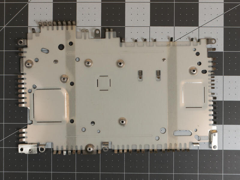
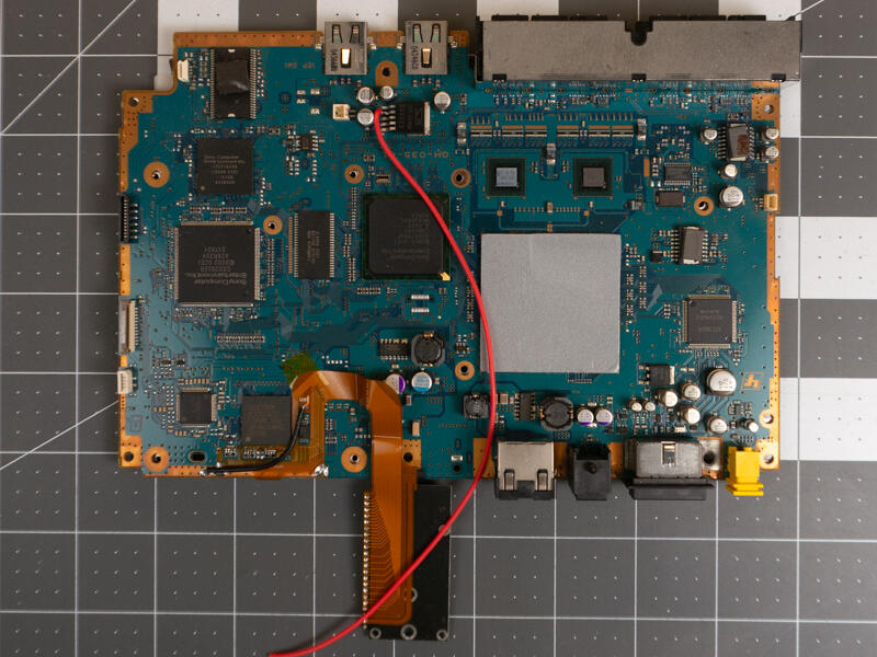

Place the board on top of the lower shield.
Step 5.2 Bend the shield away from the flex cable
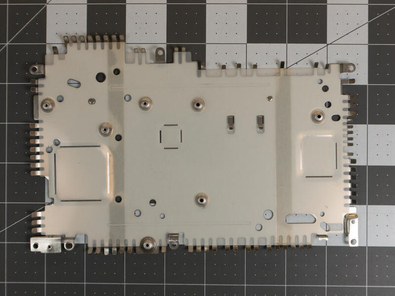
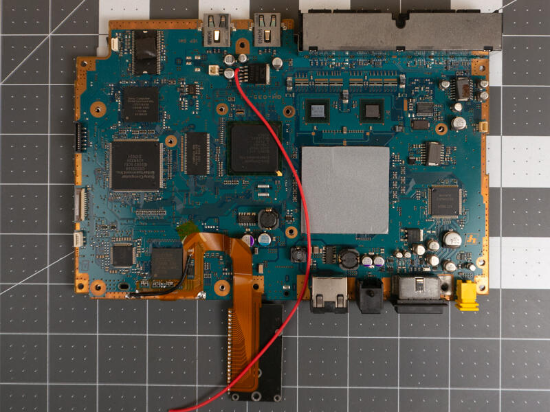
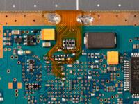
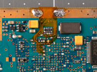
Inspect and slightly bend away the grounding fingers on the lower shield if they look like they will rub against the flex cable.
Step 5.3 Bend the flex cable
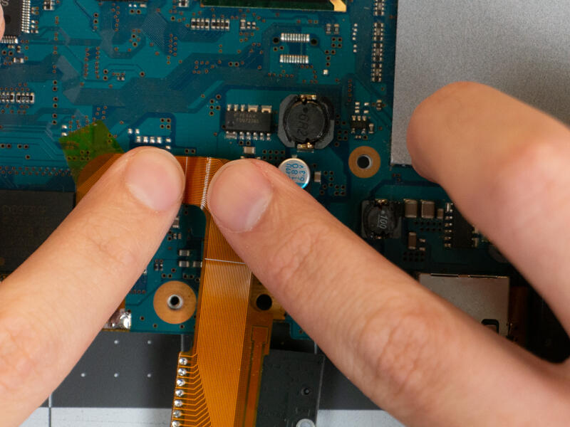
Gently bend the flex cable as shown along the lines.
Solid indicates the internal bend and dashed the outer bend.
DO NOT SHARPLY CREASE THE FLEX CABLE AS THIS MAY BREAK THE TRACES.
You do not need to bend the dotted line near the M.2 adapter yet.
Step 5.4 Check thermal pad placement
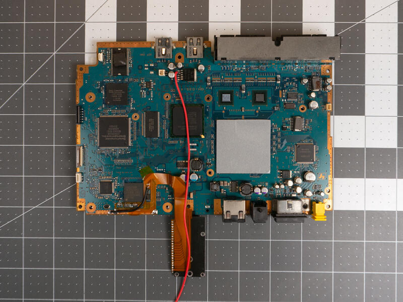
Check the placement of the thermal pads.
Step 5.5 Assemble top shield
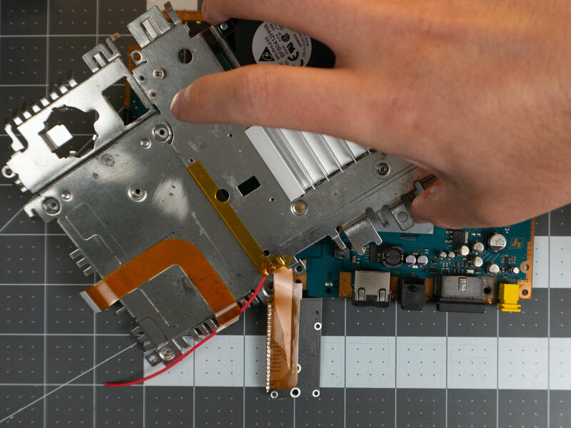
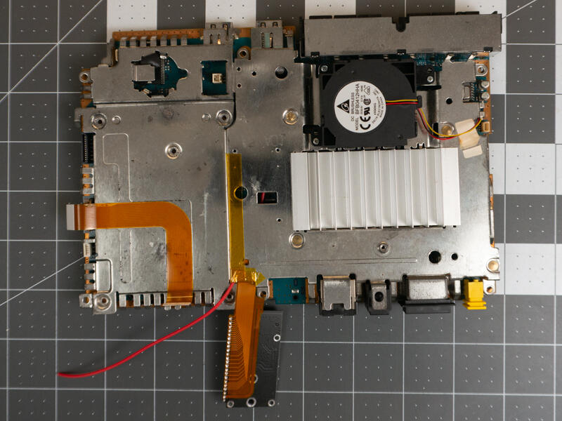
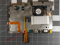
Carefully thread the flex cable through the gap and lower the top shield into place.
Step 5.6 Bend the shield away from flex cable
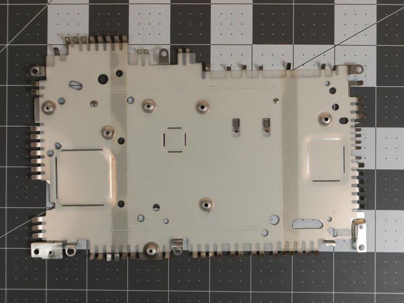
Inspect the grounding fingers on the top shield and bend them away if they contact the flex PCB.
Step 5.7 Install DVD drive screw
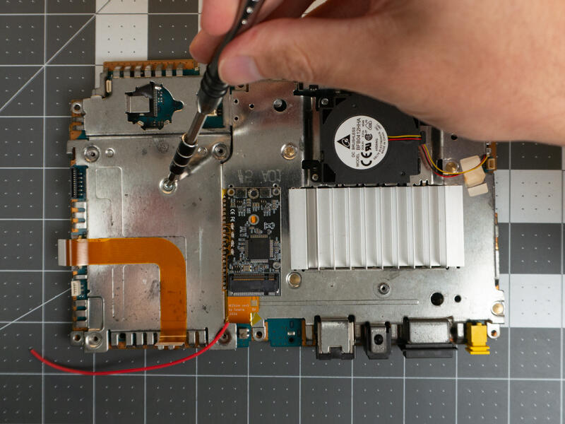
Install the screw under the DVD assembly but do not tighten it fully.
This is just to make handling the PS2 easier.
Step 5.8 Affix the M2Slim adapter board to the shielding
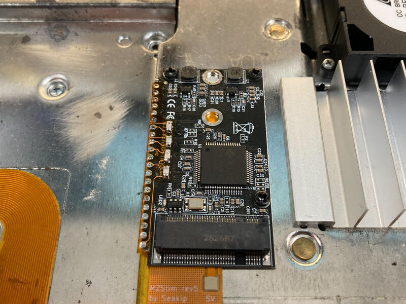
Fold the M2Slim over and into place over the holes. There should be just enough slack in the flex cable to allow this.
You may gently fold the cable around the edge of the shield but the less you bend the cable the better.
Do not create a sharp crease in the flex cable.
Use 3 self tapping screws to secure the board in place.
Do not tighten fully to allow for alignment in the next step.
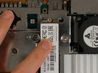
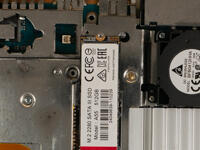
Step 5.9 Align the board with the SSD retention post.
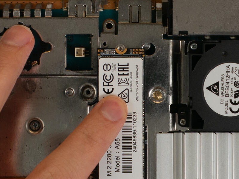
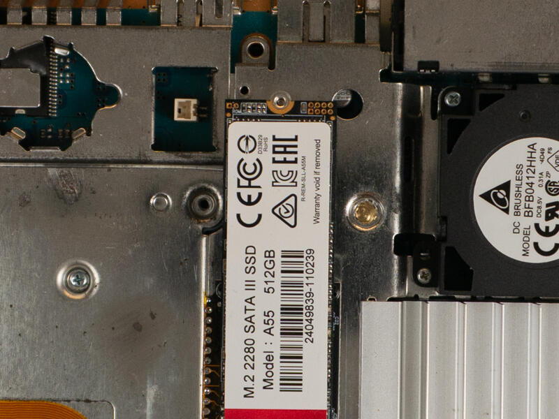

Firmly seat an M.2 SSD into the adapter.
Adjust the adapter and SSD together to align with the post.
Hold down the M2Slim adapter board at the connector and remove the SSD.
Tighten all the screws down.
Step 5.10 Install the underside heatsink screws
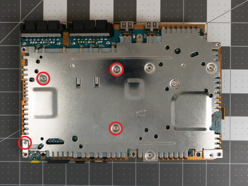
Flip the board over and install the 4 screws around the heatsink.
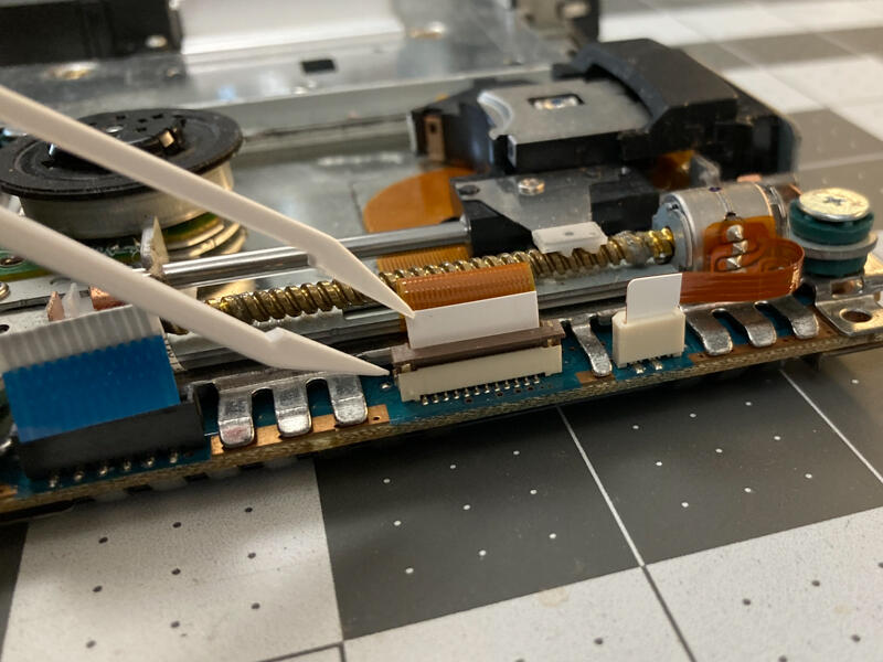
Step 5.11 Attach the disk drive laser ribbon cable
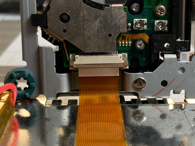
Tighten the screw under the DVD assembly.
Align the drive assembly as shown and slide in the flex cable.
Close the brown retention actuator.
Step 5.12 Install disk drive spacers
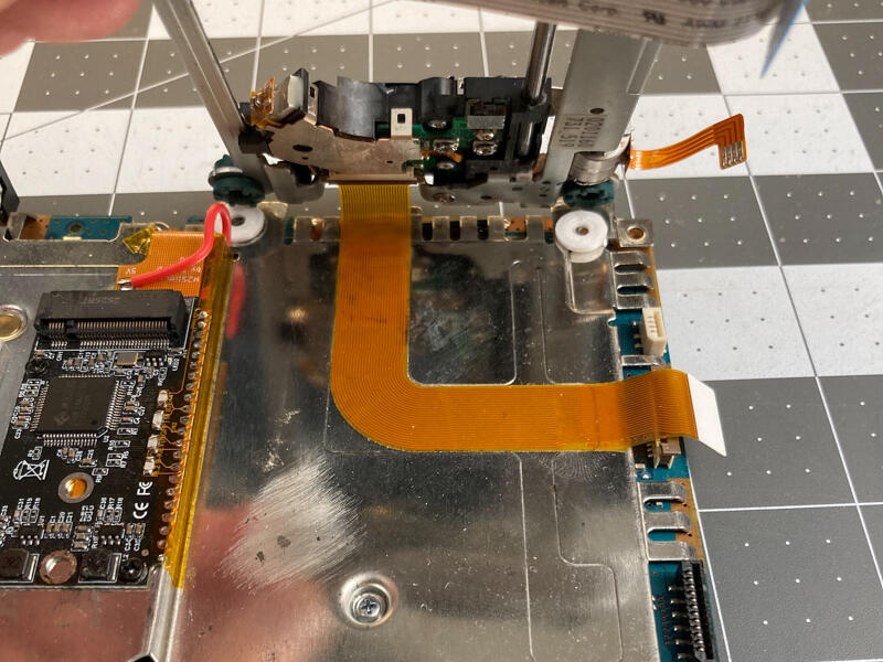
Place the 4 spacers on the screw holes for the DVD drive.
Step 5.13 Install disk drive
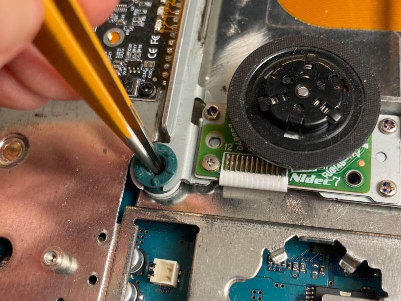
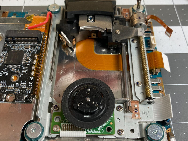
Carefully place the DVD drive over the screw holes to keep the spacers aligned.
A tweezer helps if any get bumped out of place.
Install the 4 disk drive screws.
Step 5.14 Install disk drive flex cables
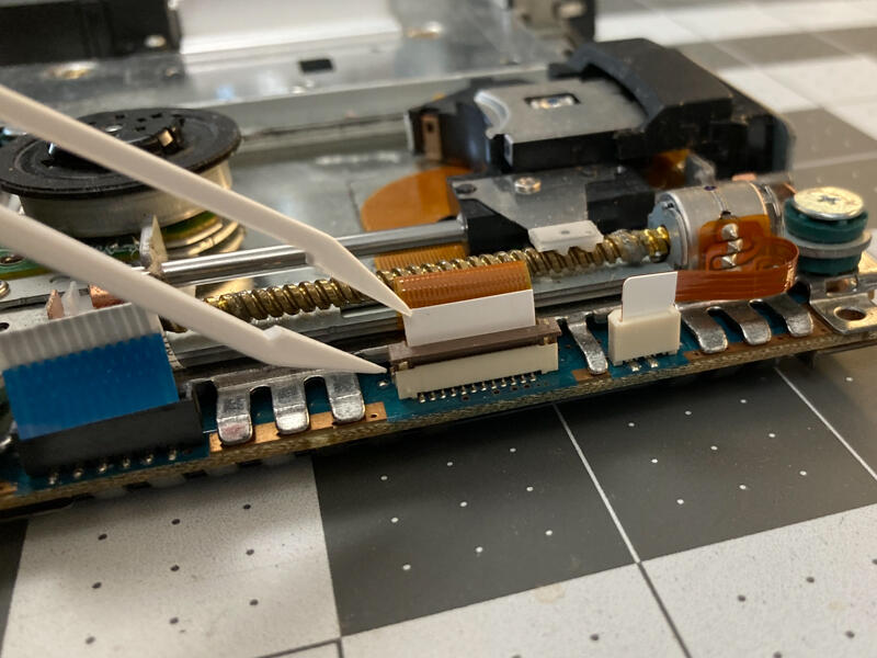
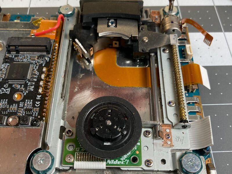
Carefully place the DVD drive over the screw holes to keep the spacers aligned.
A tweezer helps if any get bumped out of place.
Install the 4 disk drive screws.
Step 5.15 Connect CMOS and Fan
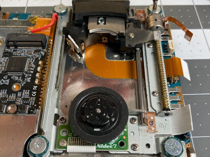
Connect the Fan and CMOS battery.
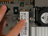
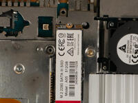
Step 5.16 Check disk clearance.
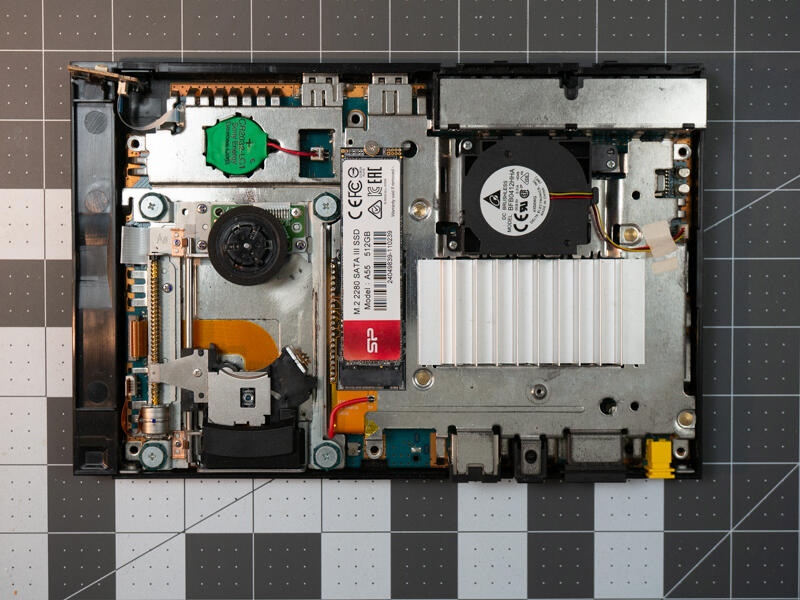
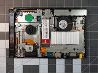
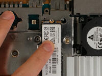
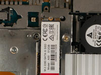
Install an SSD.
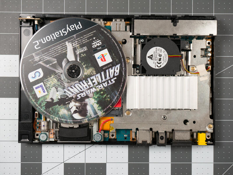
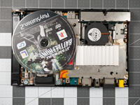
Place a disk in the drive
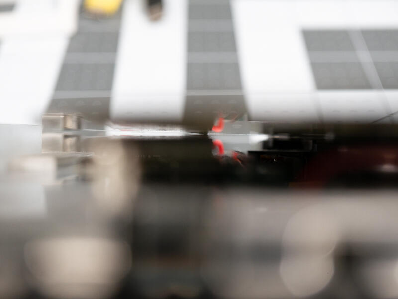
View from the side to confirm clearance above the drive.
The label on this SSD is starting to peel and would scratch the disk if used. However removing it often voids warranty. Taping it down may be a good option if you encounter this problem.